


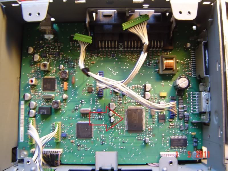
after the screws are removed gently pick up the tape deck and unplug the 2 connectors on the unit by pulling them straight out
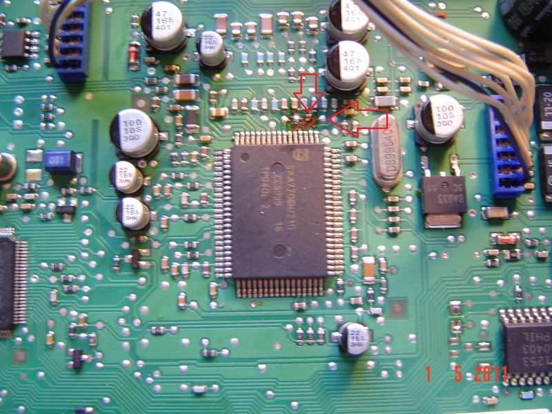
we now have access to the main board of the radio and you can finally see the chip we are interested in
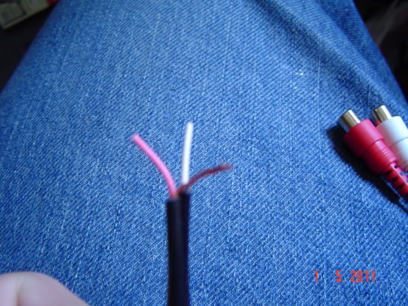
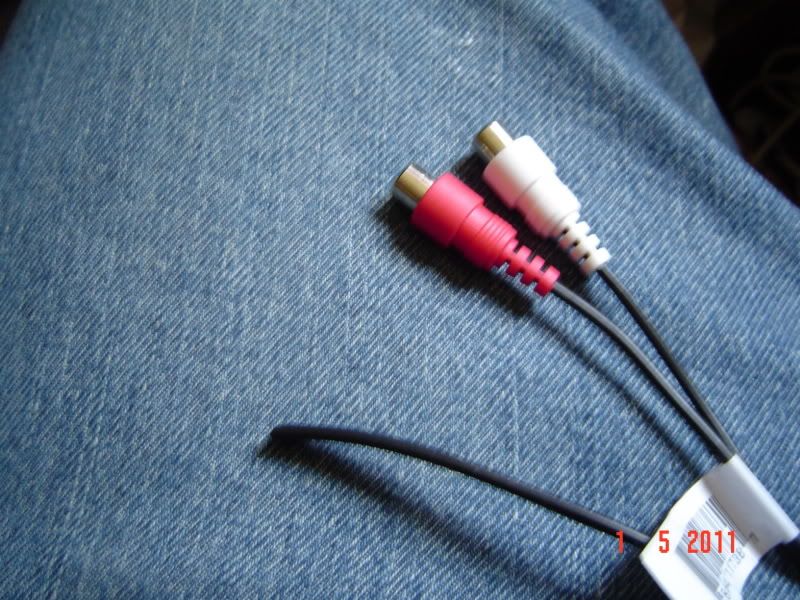
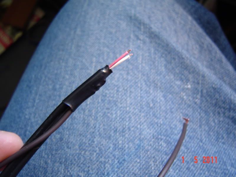
now its time to make the AUX input wire, i used a rca to 3.5 mm jack wire i got from ebay for 7$. first thing i did was cut off the 3.5mm jack end
i then used a wire stripper to strip the plastic casing from the 2 wires exposing 2 smaller coated wires (left and right signal wires) and a bunch of uncoated wire (ground wire). Next step is to gather the ground wire together like so and strip the ends of the 2 signal wires
solder a wire extension to the ground wire and use a peace of heat shrink to seal it
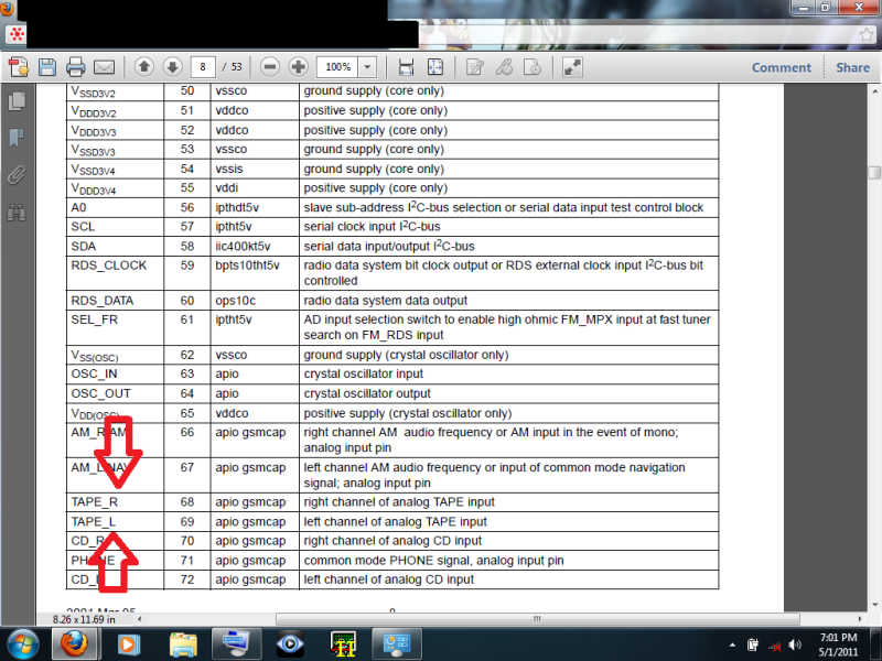
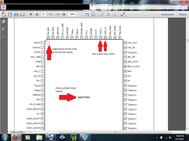
now we are ready to do the mod. here is some more info from the data sheet on the chip, along with the 2 points we want
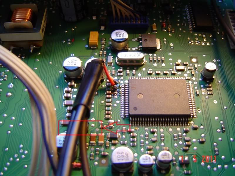
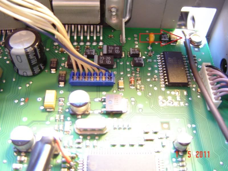
on the radio main board the points we want are right here
solder the 2 signal wires to the 2 solder points
then solder your ground to a ground point on the board, i chose this ground pad
apply hot glue here to help the wire stay in one place and not stress the solder points


 Reply With Quote

