-
1990 C1500 Gauge Cluster wiring Diagram Needed.
Just about finished my lq4/4l80e swap and have the last bits of wiring to finish. Does anyone have a diagram for the cluster wiring harness? I need to find the speedo wires, and I don't want to tap the wires on the outside of the engine bay.
-
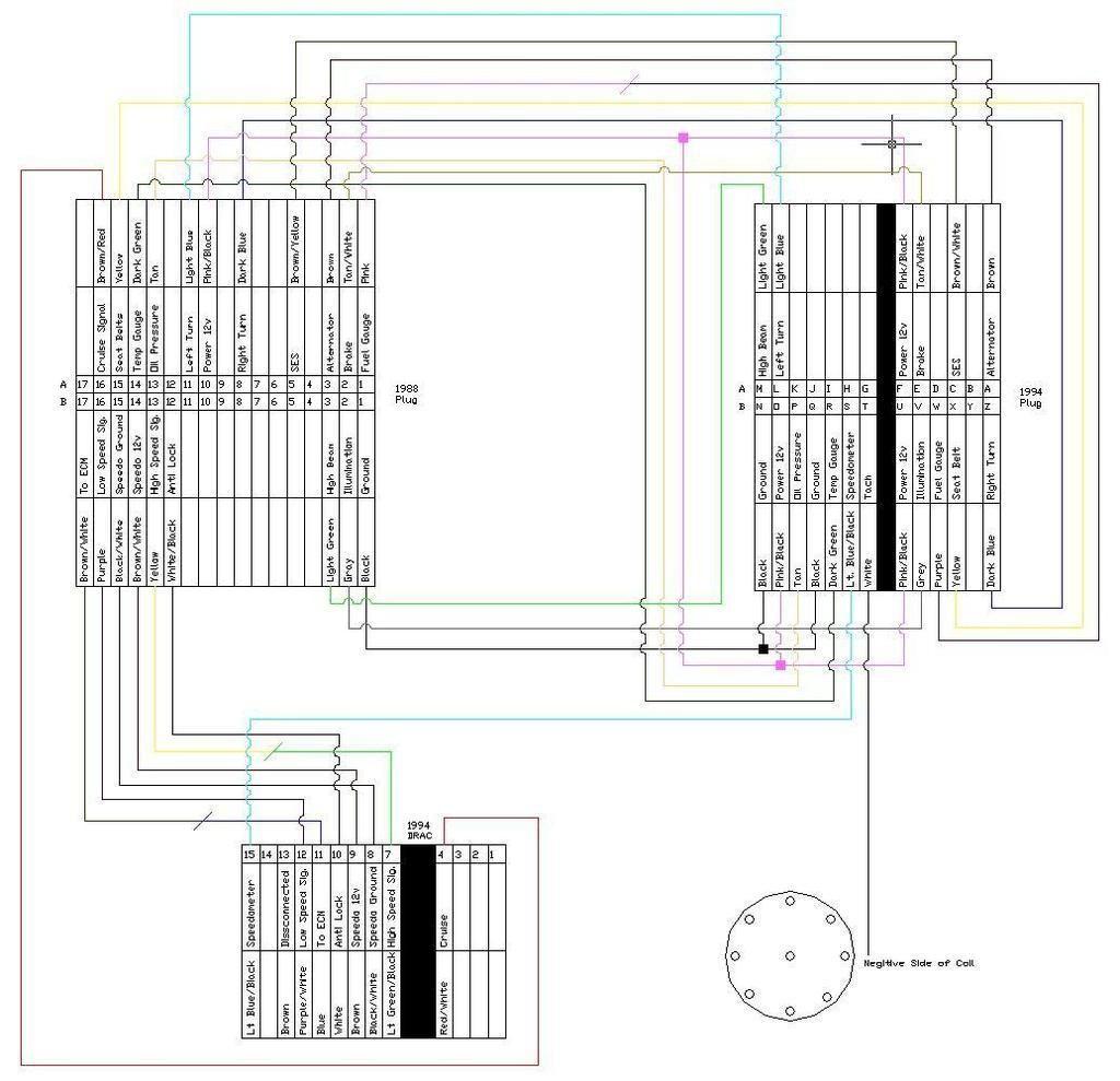
This image is courtesy of 88GMCtruck on gmt400.com.
-
Is the plug identification the same throughout the model years? My truck didn't have a drac module.
-
That diagram is to add a drac so that you can run 92-94 gauges with a tach. Sorry, I should have mentioned that. I believe that the 88 plug is the same.
-
Tapped the output from the ECU to the two wires for the speedometer on the cluster, when driving the gauge sweeps around and doesn't function properly. Has anyone had any luck tapping the speedometer output into instrument cluster directly?
-
I have had quite a bit of experience with the 88-90 speedometer wiring. I swapped in an LS1/T56 into my 88 C1500. First the 88-90 are special, the gauge cluster gets the speedometer signal first, conditions the signal and sends it to the RWAL brakes and cruise control. 88-90 does not have a DRAC and the plug on the back of gauge cluster in not the same.
Your speed sensor wire coming out of the PCM will not be used, just tie it up out of the way.
The purple and yellow twisted pair of wires coming from the trans speed sensor are the key to making your speedo work, the original sensor produced an AC signal using a 40 tooth reluctor ring on the trans output shaft, located inside trans tail.
I don't have any experience with the 4L80E but if it has a speed sensor with a 40 tooth reluctor ring and a two wire plug it should be sending the same signal the original sensor had.
In my case I had to mount a speed sensor on rear differential/driveshaft to get the proper 40 tooth per revolution signal.
-
I ended up tapping into the Low/High VSS signal going to the ECU, I havent had a chance to test it yet... But I think it's going to work.
 Posting Permissions
- You may not post new threads
- You may not post replies
- You may not post attachments
- You may not edit your posts
Forum Rules


 Reply With Quote