+ Reply to Thread
Page 1 of 4 1 2 3 ... LastLast
Results 1 to 10 of 36

Thread: Stock R4 compressor MOD and E-fan hook up HOW TO

  1. #1
    Join Date
    Mar 2013
    Location
    Long Beach California
    Posts
    637

    Stock R4 compressor MOD and E-fan hook up HOW TO

    ok so ive started several threads trying to figure this all out and now i finally got everything hooked up and running and here is the final HOW-TO like i promised all consolidated into this one thread.

    This is to get your factory R4 compressor/bracket from your TBI motor installed on the new LS transplant for very little money. This was done on my 95. I have to note that on all the aftermarket setups ive seen, they all say 94 and prior and none for 95 up. i personally dont know what the difference is between the years but they cant be all that different so i would think this will still work for pre-95... But dont quote me on that. it should at least get you very close.

    Parts needed:
    Portaband/sawzal/hacksaw/grinder - any or all will do
    2-1/2" hole saw
    1- M10 x 1.5 x 90mm bolt (3 washers are required otherwise bolt will bottom out or you can cut tip off bolt)
    1- M10 x 1.5 x 20mm bolt (i had this from some part off the LS)
    1 or 2 3/4" washers
    1- 995k6 serpintine belt


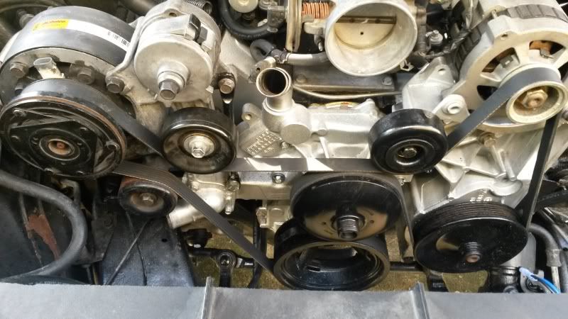
    First we have to trim some fat off the bracket. Take out the compressor by removing the 3 retaining bolts. there is one side on the bolt head that is ground flat which will allow it to slide past the clutch. Then remove the tensioner/pulley and idler pulley and hardware. Set the idler(smaller one) and bolt/spacer aside as this will be re-used. Now cut the lower and side portions of the bracket off and discard. I have a portable band saw which makes this really simple but a hack saw or sawzawl will work too, it will just takes more time im sure.


    We will be using the stock LS tensioner which is in the way of the R4 bracket. So the bracket will need to be notched. This is where some of you may need to get creative. I used a hole saw (i think it was 2-1/2"). This was the most difficult part of the modifiction. I wish i could give an exact spot where to start the drill but just make sure the outside of the notch ends up close to what you see in the pic. Some touch up grinding may be necessary for clearance/adjustment. I cut all the way to the back wall of the bracket. No this dis not take away the structural integrity of it. The bracket is still very sturdy. Now just file all the sharp edges and your are ready for paint. Thats it for the bracket.


    Next you will need to remove the LS tensioner off the water pump for minor trimming. Remove the pully and set it with the other idler pulley you put aside earlier. First is the extra chunk on the front which normally sits behind the grooved pully. We will be putting on the smooth idler pully from the old motor which will hit this unless cut off. again, portaband made this easy but grinder should work also.

    You can see where i cut.

    Plenty of clearance now.

    Next will be to trim the little tab on the back down just a bit. I think its a support tab so i left that little bit left to help out.


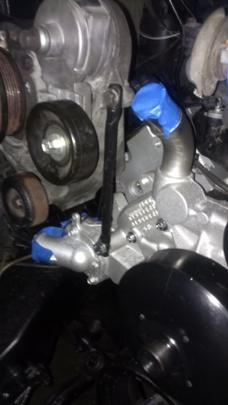
    We need to make a support brace next. It will be going from the pump bracket to the head. at the moment i am only using one brace and it seems to be very strong. but there is some vibration when the pump is running and i will probably be putting one going rearward and mounting it to a bolt hole on the side of the head. you may want to do this also but that is up to you as it works fine without it. i have all kinds of scrap metal laying around so i dug through and found a piece of 3/16-1/4" flat stock. i cut it around 6" long, drilled a hole in each end for the bolts and put about a 7/8" offset in it.


    the third hole in the middle was already in the scrap steel but it doesnt affect anything.

    Thats all the fabrication required. Now its time to install everything. First is to take the 20mm-ish bolt, put it through one end of your support brace and into the far right bolt hole in the head. This is much easier to do before pump bracket is in place. Dont tighten yet. Now take the 90mm bolt (and washers if you didnt cut tip off bolt) and put it through right side hole in pump bracket and into top left bolt hole in head as shown. Again do not tighten yet.


    this is the reason for the huge notch. Fits nicely around the tensioner.

    Next set the compressor in the bracket and push the 3 long bolts through. slip the support brace over the bolt and install the 3 nuts. All the hardware can now be tightened down. heres a bad pic of the support brace...


    You can now put the pullies back on But you will be reversing them. The bearings are the same size. The smooth smaller TBI pulley goes on the LS tensioner. you might need 1 or 2 3/4" washers depending on thickness to space the pulley forward a bit. Mine was still slightly touching the tensioner. You will be re using the LS bolt but the front washer will be from the TBI pulley. This is the order:


    This is the washer i had that slipped right over the boss.

    Now put the LS grooved pulley on the R4 bracket where the smooth idler used to go. you will be using the TBI bolt and rear spacer and NO front washer. Its not needed. this is the order:


    Last but not least is the Belt which took me 2 days of trial and error to figure out. Now this belt will work with the setup i have just mentioned. but if you change things, the belt will have to be changed as well. I ended up with autozone duralast part #995k6. i didnt want to get an expensive one in case things didnt line up and it ate the belt. So far so good. i dont notice any unusual wear and it doesnt slip at all. so i think you would be alright to go with a better brand as long as its the same length but thats your choice. Follow the belt in the pics for the propper re-routing i came up with:


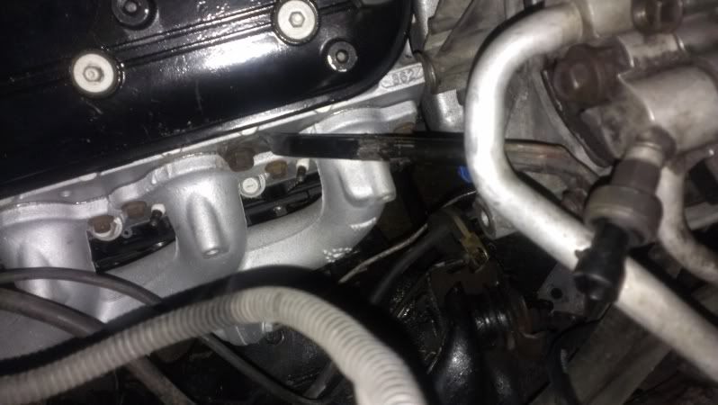
    The coolant hose gets super close to the belt and would flop around and started cutting into the hose. so a support will need to be made.


    the support i made but im sure you can figure something out depending on your setup.

    the stock hoses SHOULD work as the compressor is in almost the exact same position so modification of the hoses shouldnt be nesessary. But due to the location of my PCM and fuse block, i had to get my lines modified. Here is a pic for reference:


    Im pretty sure that is all to get it mounted and running. If i remember something i will update. Next post will be for those running electric fans and how to hook them up to work with the AC.
    Like Tumbler in "Gone in 60" I'll drive anything with wheels or without

    My 95 ECSB LQ9 build thread - http://www.ls1truck.com/forums/lsx-t...to-95-obs.html
    CALI LEGAL ENGINE SWAP!
    Stock 03 LQ9, DBW, 95' 4l80e w/ Transgo shift kit, 2010 50# GM injectors, 2800 Circle D stall, Spectre CAI, Upgraded trans cooler, Home-made E-fans/shroud, Dual EP-381 fuel pumps w/Home-made hotwire kit
    NEXT ON LIST: Dual Battery setup, CAM/Valvetrain upgrade, Build my own rear mount turbo, TRU-TRAC, HIT THE STRIP!!!

  2. #2
    Join Date
    Mar 2013
    Location
    Long Beach California
    Posts
    637
    If your running your clutch fan with a shroud then this wont apply to you. but for those of us using electric fans, there needs to be a way to have them turn on like they should under all conditions; engine temp- Low speed and High speed; AC control High speed.

    If you have e-fans, they will both kick on "low speed" when engine temp reaches around 106°C (223°F) then high speed if temp reaches 110°C (230°F). The computer is what controls this on the LS motors. It also tells the fans to kick on High speed any time the AC is activated. The problem with this is that unless your swap has ALL of the data lines and computers (pcm,bcm,tcm) there is no way to tell the pcm when the ac is activated as its input is by DATA and not a 12v or ground source. you can read more into that in this link http://www.ls1truck.com/forums/lsx-t...tegration.html there is a possible solution at the end which one of thee days i would like to try but i need to find a tuner with the correct software. so untill then, i have came up with a simple and effective solution.

    List of parts to get it running

    1) 2 - S.P.S.T relays rated above the amperage of your fans for Low and High speed operation
    2) 1 - S.P.D.T relay for switching between speeds
    3) 1 - S.P.S.T relay for AC high speed bypass
    4) 3 - 50V 1amp silicone rectifier diodes

    If you already have your fans up and running like this then all you need is #3 & 4 to add to the circuit for the AC bypass

    This is the diagram to make the two fans work with the engine temperature. If your adding fans, you will need to add two pins to the pcm and have the pcm programmed to control the fans. pin 42 Blue = low speed, pin 33 green/red = high speed


    Now we want to keep that circuit for normal driving but if we want to turn on the AC, the fans need to kick on High no matter what as long as the AC is being called for in order to cool the condenser. so what were are going to do is add another relay to override the existing circuit and 3 protections diodes. Here is my new revised diagram:

    The red wires are the only wires that were added and the new relay is the one in the lower right corner. The green triangles for those not familiar with electrical diagrams are the 3 diodes, D1-D3.

    If you follow the circuit, im picking up a positive 12v that actuates the compressor clutch. we are just tapping into that to tell the new relay when to actuate so it wont draw much current. this is where i grabbed the power from.

    i soldered a splice into the blue wire coming off the back high pressure switch. This allows the fans to keep running even if the switch opens during cycling since your still calling for it inside the cab. That way air is still being pulled through the condenser and the fans dont keep kicking on and off.

    When the new relay is actuated, it allows a ground to go to all 3 original relays (completely bypassing the computer) in turn forcing them to actuate and put the fans in high speed. wahoo right? its working! well what do the diodes do you ask? well D1 and D3 are there to protect the pcm. Diodes are directional only letting electricity to flow one way. i know this is a ground path from the pcm but i am tapping into a circuit that goes directly to the pcm and i dont want any unwanted voltage (accidents happen) backfeeding into it. D1 and D2 are not NESESSARY for the fans to work but they are there for MY piece of mind and i HIGHLY suggest you use them too so you dont risk harming your expensive PCM.

    D2 on the other hand is necesary.... Ask me how i know... lol. Anyway, If you dont have it, when the pcm supplies the ground for the low speed, it will go to the low speed relay but it will also travel through all your newly added wires and actuate the other 2 relays thus kicking them into High even though the pcm is telling them low. The diode will stop the ground from going to the switching/high speed relays during low speed, but allow the ground to come the other way from your new BYPASS relay for the AC.... If this is a bit confusing to you, dont worry, just hook it up like in the diagram and you will be good to go.

    just remember the diodes are DIRECTIONAL so polarity matters. i put a positive and negatice symbol on each side of the diodes in my diagram so you know which way to solder them in. The cathode is the negative side and on the actual diode itself has a grey line on one side. The side with the gray line is the cathode (negative side). Here is a pic of the Package:


    another note to add is that another thing the pcm would do when it got a signal saying the AC was called for was that it raised the RPM of the motor a bit to compensate for the load of the pump. Ive heard of guys having problems with idling while the pump is actuated and some dont.... I have a LQ9 in mine. I dont know if the added torque of the 6.0 is what makes it OK or if im just lucky or what. but it will not stall out at a stop in gear. BUT it does cause a slight vibration throughout the truck like its struggling a little bit. if i give it a LITTLE bit of gas, the vibration goes away. so i think im going to have my tuner raise the idle a bit to help compensate for this. But remember this will raise the idle constantly even without the AC. I think i can live with that since it wont be much. Just something to think about. Hope this helps some of you out. I sure am enjoing my AC.
    Last edited by kewljay223; 09-30-2013 at 08:28 PM.
    Like Tumbler in "Gone in 60" I'll drive anything with wheels or without

    My 95 ECSB LQ9 build thread - http://www.ls1truck.com/forums/lsx-t...to-95-obs.html
    CALI LEGAL ENGINE SWAP!
    Stock 03 LQ9, DBW, 95' 4l80e w/ Transgo shift kit, 2010 50# GM injectors, 2800 Circle D stall, Spectre CAI, Upgraded trans cooler, Home-made E-fans/shroud, Dual EP-381 fuel pumps w/Home-made hotwire kit
    NEXT ON LIST: Dual Battery setup, CAM/Valvetrain upgrade, Build my own rear mount turbo, TRU-TRAC, HIT THE STRIP!!!

  3. #3
    Just finished this same set up today. I had to change the pulleys around in my set up so that the belt doesn't touch itself when passing thru the idle pulleys and the water pulley. I also was able to heat the base of the upper water neck of the water pump and turn it slightly, so I would have clearance and it would not rub on the belts or pulleys. I moded the brackets that were used on the bottom of my old trans and old 4.3. I heated them with a torch til they glowed red hot and hit them with a sledge hammer. I did a front and rear bracket for the a/c compressor.


    Last edited by droopyzda1; 10-01-2013 at 03:34 AM.

  4. #4
    Join Date
    Jun 2011
    Location
    Rogers, Ar
    Posts
    51
    I would let the pcm control the fans based on ac pressure and speed like stock. Cooling fans dont normally need to be on high and they dont need to be on above 30 mph for anything.

  5. #5
    Join Date
    Mar 2013
    Location
    Long Beach California
    Posts
    637
    nice man. its a hell of a lot cheaper and more gratifying doing it yourself huh? congrats. your rearward brace is exactly the one i want to add. hopefully it will help stop the vibration. i got my scanner out today and did some testing. she idles without AC right at 600. as soon as i kick the AC on, idle drops to about 450 but she will raise right back up on her own. same thing when in gear. so im thinking the vibration is from the bracket moving around a bit. so i will get that second support on there asap.

    question though. why did you need to turn the waterneck? your belt is routed WAY below it.... But anyway, its good to see another setup on here. what year is that for? 95+?
    Like Tumbler in "Gone in 60" I'll drive anything with wheels or without

    My 95 ECSB LQ9 build thread - http://www.ls1truck.com/forums/lsx-t...to-95-obs.html
    CALI LEGAL ENGINE SWAP!
    Stock 03 LQ9, DBW, 95' 4l80e w/ Transgo shift kit, 2010 50# GM injectors, 2800 Circle D stall, Spectre CAI, Upgraded trans cooler, Home-made E-fans/shroud, Dual EP-381 fuel pumps w/Home-made hotwire kit
    NEXT ON LIST: Dual Battery setup, CAM/Valvetrain upgrade, Build my own rear mount turbo, TRU-TRAC, HIT THE STRIP!!!

  6. #6
    Join Date
    Mar 2013
    Location
    Long Beach California
    Posts
    637
    Quote Originally Posted by Oldspimp View Post
    I would let the pcm control the fans based on ac pressure and speed like stock. Cooling fans dont normally need to be on high and they dont need to be on above 30 mph for anything.
    The pcm still does controls the fans like stock. the only thing i did was make them turn on high when the AC is on. do you have another suggestion on where i should tie the wire in that would actuate the BYPASS relay and any reason why that would be of better benefit than what i have shown? The only benfit i could maybe see is that they wouldnt be on constantly... ????
    Like Tumbler in "Gone in 60" I'll drive anything with wheels or without

    My 95 ECSB LQ9 build thread - http://www.ls1truck.com/forums/lsx-t...to-95-obs.html
    CALI LEGAL ENGINE SWAP!
    Stock 03 LQ9, DBW, 95' 4l80e w/ Transgo shift kit, 2010 50# GM injectors, 2800 Circle D stall, Spectre CAI, Upgraded trans cooler, Home-made E-fans/shroud, Dual EP-381 fuel pumps w/Home-made hotwire kit
    NEXT ON LIST: Dual Battery setup, CAM/Valvetrain upgrade, Build my own rear mount turbo, TRU-TRAC, HIT THE STRIP!!!

  7. #7
    Nice write-up kewl, im subscribing for future refrence.
    Mine right now is routed just like droopy, I mean exactly down to the blue tape closing up the water pump ports lol.
    He turned the neck not for belt clearance but for the tensioner to clear.


    Droopy what pullies did you swap and what size belt did you use if you dont mind me asking.
    I need a belt and to turn my water neck still.

    And oldspimp, the ls computer needs to have the ac signals from the original vehicles ac ccontrollers.
    Thats not easy to do on these older trucks since most of their ac signals are voltage + and - signals not serial data that the ls pcm requires.

  8. #8
    Thats exactly why I turned the water neck. For pulley clearance. As far as the belt goes, I forgot. !! Actually Mickeymotormount was the one who told me the part number and I went to the auto part store. They did not have the exact one but cross referenced it and it fit perfectly. I also got a clothes line and wrapped it around the pulleys the way I wanted it routed and that was the same size that mickey stated.

    As for the idler pulleys, I simply mixed and matched the ones from the 5.3 set up and the ones off my old 4.3 tbi pulleys and they worked perfectly.

  9. #9
    Join Date
    Sep 2012
    Location
    Quakertown, Pa.
    Posts
    363
    Nice write-up on the A/C 'Jay. Just goes to show you, there's more than one way to skin a cat.

    Droopy did the same setup as I did. He used the original 4.3/5.7 liter tensioner. That requires turning the water neck some for clearance. And by comparing pics I noticed that your compressor is higher and closer to the water neck than ours.
    '93 Chevy 1500 4X4 ECLB with a '99 Silverado LQ4 6.0 and '99 Escalade 4L60E. SOLD IT!!

    New toy: 2001 2500 HD 4X4 Extended Cab Long Bed


    John

  10. #10
    Join Date
    Jun 2011
    Location
    Rogers, Ar
    Posts
    51
    I guess I skipped over the data line part of the thread. I thought it was just a matter of adapting high and low pressure switches and sending signal to the pcm, my bad. It just seems wasteful to me to have the fans on high when your on the hi-way cause all thats doing is slowing down air flow. I bet relays could be directly wired to pressure switches for a little more control over the fans, I think some old school switches are even adjustable.

+ Reply to Thread

Posting Permissions

  • You may not post new threads
  • You may not post replies
  • You may not post attachments
  • You may not edit your posts